arduino硬件总结
arduino 支持中断,ADC,PWM,I2C,spi,串口等功能,现对如上功能进行总结。其中重点是I2C,spi,串口。
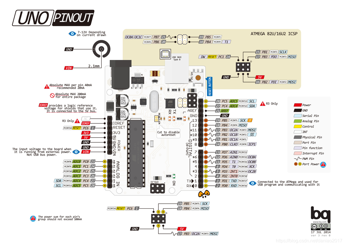
硬件引脚图,如下:

基本资料可以参考arduino常用函数的总结 更详细的资料可以参考arduino编程手册
串口通讯
具体可以参考博主的博客 GPS模块的应用 将arduino uno的数据上传到云平台 这些都是用串口进行数据收发的。
I2C
可以参考两个arduino之间的I2C通信 深入浅出I2C通信
SPI
带总结
中断函数
基本了解
对突发事情的回应,可以用来测速
PIN2 -> INT0
PIN3 -> INT1
实现测速
1
2
3
4
5
6
7
8
9
10
11
12
13
14
15
16
17
18
19
20
21
22
23
24
25
26
27
28
29
30
31
32
33
34
35
36
37
38
39
40
41
42
43
44
45
46
47
48
49
50
51
52
53
54
55
56
/***************************************
*M0C70T3中断,测速实验
* OUT -> PIN2
* 作者:小刘同学
**************************************/
/*-----------变量设置----------*/
unsigned long time_t = 0, old_time = 0; // 时间标记
int Counter ; //编码器计数
float speed_t; //速度
void setup() {
   Serial.begin(9600);  //方便调试
   //中断0,pin2
  attachInterrupt(0,Speed_CallBack, FALLING);
}

void loop() {
SpeedDetection();
}

/***************************************************
 函数功能:速度计算
 输入:无
 输出:无
 返回值:bool
 note :小刘同学,2020-12-20
 参考:
 https://blog.csdn.net/qq_16775293/article/details/77688784
 **********************************/
bool SpeedDetection()
{
  time_t = millis();//以毫秒为单位,计算当前时间
  if(abs(time_t - old_time) >= 1000) // 如果计时时间已达1秒
  {
    detachInterrupt(0); // 关闭外部中断0
    //把每一秒钟编码器码盘计得的脉冲数,换算为当前转速值
    //speed_t =(float)Counter/60;//小车车轮电机转速
    speed_t = Counter;
    Serial.print("speed:");
    Serial.println(speed_t);

    //恢复到编码器测速的初始状态
    Counter = 0;   //把脉冲计数值清零,以便计算下一秒的脉冲计数
    old_time=  millis();     // 记录每秒测速时的时间节点
    attachInterrupt(0, Speed_CallBack,FALLING); // 重新开放外部中断0
    return 1;
  }
  else
    return 0;
}
/**********************************
 函数功能:编码器中断服务函数
 *********************************/
void Speed_CallBack()
{
  Counter++;
}
ADC
ADC模块可以将输入的模拟信号转化成数字信号。可以读取如光敏传感器,温度传感器的值。10位,0-1023,0-5v
读取光敏传感器的值
1
2
3
4
5
6
7
8
9
10
11
12
13
14
15
16
17
18
19
20
21
22
23
24
25
26
27
28
/*********************************
 * 光敏电阻读值,并用控制led延迟时间
* OUT -> A0
* 作者:小刘同学
 ****************************/

int sensorPin = A0;    // select the input pin for the potentiometer
int ledPin = 13;      // select the pin for the LED
int sensorValue = 0;  // variable to store the value coming from the sensor
/*-----------变量设置---------------*/
void setup() {
  Serial.begin(9600);  //方便调试
  pinMode(ledPin, OUTPUT);
}
/*-----------函数初始化-----------*/
void loop() {
  // read the value from the sensor:
  sensorValue = analogRead(sensorPin);
  Serial.println(sensorValue);
  // turn the ledPin on
  digitalWrite(ledPin, HIGH);
  // stop the program for <sensorValue> milliseconds:
  delay(sensorValue);
  // turn the ledPin off:
  digitalWrite(ledPin, LOW);
  // stop the program for for <sensorValue> milliseconds:
  delay(sensorValue);
}
pwm舵机控制
1
2
3
4
5
6
7
8
9
10
11
12
13
14
15
16
17
18
19
20
21
22
23
24
25
26
27
/***************************************
*舵机控制实验
* OUT -> PIN9
* 作者:小刘同学
**************************************/
/*-----------包含头文件---------------*/
#include <Servo.h>
Servo myservo;  // 定义Servo对象来控制
/*-----------变量设置---------------*/
int pos = 0;    // 角度存储变量
/*-----------函数初始化-----------*/
void setup() {
  myservo.attach(9);  // 控制线连接数字9
}
/*-----------函数循环-----------*/
void loop() {
  // myservo.write(180);
  for (pos = 0; pos <= 180; pos ++) { // 0°到180°
    // in steps of 1 degree
    myservo.write(pos);              // 舵机角度写入
    delay(5);                       // 等待转动到指定角度
  }
  for (pos = 180; pos >= 0; pos --) { // 从180°到0°
    myservo.write(pos);              // 舵机角度写入
    delay(5);                       // 等待转动到指定角度
  }
}

